Windows 10 IoT and Adafruit LPD8806 RGB LED Strip

Introduction
I got one metre of the Adafruit LPD8806 RGB LED strip with a NetDuino Plus 2 many years ago with bold visions of colourful Christmas decorations on the front of the house. After some success with blinding myself, they were forgotten about when child #1 arrived. The NetDuino suffered the same fate as it couldn’t talk HTTPS.
When Microsoft announced they would support Windows 10 IoT on the new Raspberry Pi 2, the wheels started turning again.
The code is a shameless hack job of the netduino helpers project on CodePlex. I’ve stripped it down to just setting static colours across all of the LED’s. I am not planning any animations yet.
Hardware
- Raspberry Pi 2 Model B - Element 14.
- 2A Micro-USB power supply - Element 14.
- Micro SD card for Windows 10 IoT - Scorptec
- LPD8806-based RGB LED strip - Adafruit
- 5V 10A power supply - Adafruit
- Female DC Power adapter - Adafruit
- Jumper wires
Wiring
Already had wires soldiered to the LED strip from previous experiments (Adafruit tutorial), so all I needed was the Raspberry Pi 2 pinout diagram on the Windows IoT site:
- Connect the black ground (GND) to any ground PIN of the RPi2 - I used 39.
- Connect the yellow clock (CI) to the SPI0 SCLK (PIN 23) of the RPi2.
- Connect the green data wire (DI) to the SPI0 MOSI (PIN 19) of the RPi2.
- Connect the red +5V power wire to your power supply.
Initialisation Code
Here is the C# code for the top-level constructor and initialisation function. Have had to move SPI initialisation to its own method so we can handle the async calls.
1
2
3
4
5
6
7
8
9
10
11
12
13
14
15
16
17
18
19
20
21
22
23
24
25
26
27
28
29
30
31
32
33
34
35
36
37
38
39
40
41
42
43
44
45
46
47
48
49
public class AdaFruitLPD8806 : IDisposable
{
    private const int bytesPerPixel = 3;

    private SpiDevice spi;
    private int pixelCount;
    private int frameSize;
    private int pixelBufferEnd;
    private byte[] pixelBuffer;
    private bool disposed = false;

    protected byte[] backgroundColor = new byte[bytesPerPixel];
    protected byte[] attentionSequence = new byte[] { 0, 0, 0, 0 };
    protected byte[] latchSequence = new byte[] { 0, 0, 0 };

    public AdaFruitLPD8806(int width, int height, string spiControllerName = "SPI0", Int32 spiChipSelectLine = 0, int clockFrequency = 10000000)
    {
        this.Width = width;
        this.Height = height;
        this.pixelCount = width * height;
        this.pixelBufferEnd = (pixelCount - 1) * bytesPerPixel;
        this.frameSize = width * height * bytesPerPixel;
        this.SpiControllerName = spiControllerName;
        this.SpiChipSelectLine = spiChipSelectLine;
        this.ClockFrequency = clockFrequency;

        pixelBuffer = new byte[pixelCount * bytesPerPixel];
    }

    private int Width { get; set; }
    private int Height { get; set; }
    private string SpiControllerName { get; set; }
    private Int32 SpiChipSelectLine { get; set; }
    private int ClockFrequency { get; set; }

    public async Task Initialize()
    {
        try
        {
            await InitSpi();
        }
        catch (Exception ex)
        {
            Debug.WriteLine("Exception : {0}", ex);
        }

        pixelBuffer = new byte[pixelCount * bytesPerPixel];
    }
}
- Set up some variables and constants that describe the RGB LED strip.
- The Raspberry Pi 2 SPI port needs initialisation so we call the InitSpi() method.
- If the initialisation fails we can handle the error.
Next, we take a closer look at the SPI initialisation function.
InitSpi()
The SPI bus on the Raspberry Pi 2 is used to send a byte array of encoded RGB levels for each of the LEDs on the string and needs to be configured before we can use it.
1
2
3
4
5
6
7
8
9
10
11
12
13
14
15
16
17
18
private async Task InitSpi()
{
    try
    {
        var settings = new SpiConnectionSettings(this.SpiChipSelectLine);           /* Create SPI initialization settings */
        settings.ClockFrequency = this.ClockFrequency;                              /* Datasheet specifies maximum SPI clock frequency of 10MHz */
        settings.Mode = SpiMode.Mode0;                                              /* Not sure. Worked for me */

        string spiAqs = SpiDevice.GetDeviceSelector(this.SpiControllerName);        /* Find the selector string for the SPI bus controller */
        var devicesInfo = await DeviceInformation.FindAllAsync(spiAqs);             /* Find the SPI bus controller device with our selector string */
        this.spi = await SpiDevice.FromIdAsync(devicesInfo[0].Id, settings);        /* Create an SpiDevice with our bus controller and SPI settings */
    }
    catch (Exception ex)
    {
        Debug.WriteLine("Exception : {0}", ex);
        throw new InvalidOperationException("SPI Initialization Failed", ex);
    }
}
- Start by specifying some SPI configuration settings that I don’t fully understand. 10MHz sounds good right?
- More device discovery.
- Create the SpiDevice using the settings and bus controller.
All The Colours
Now that the SPI device is initialised, we can send some bytes to our LED strip. We only need two functions to do most of the work.
SetColor()
1
2
3
4
5
6
7
8
9
// Sets the color of the entire strip
public void SetColor(byte red, byte green, byte blue)
{
    SetBackgroundColor(redGamma[red], greenGamma[green], blueGamma[blue]);
    for (var pixel = 0; pixel < frameSize; pixel += bytesPerPixel)
    {
        Array.Copy(backgroundColor, 0, pixelBuffer, pixel, bytesPerPixel);
    }
}
- We first set up our “Background” array with each of our 8-bit colour values. We use the gamma dictionary lookup (RedGamma, GreenGamma, BlueGamma) so the colours look “correct” and to convert the 8-bit colour in to the 7-bit colour supported by the LPD8806 chip.
- Next, we copy the background colour array over to our pixel buffer that will be written to SPI in the Refresh() method.
Refresh()
1
2
3
4
5
6
7
8
9
10
11
12
13
14
// Send the internal pixel buffer to the strip
public void Refresh()
{
    if (spi == null)
        return;

    spi.Write(attentionSequence);
    spi.Write(pixelBuffer);
    var ledLatchCount = pixelCount * 2;
    for (var i = 0; i < ledLatchCount; i++)
    {
        spi.Write(latchSequence);
    }
}
- No spi means we have not yet called Initialize
- Adafruit LPD8806 strip requires a set of “attention” bytes before writing out our pixel buffer.
- Write our pixel buffer.
- Latch written bytes by sending zeros to each pixel (* 2).
Pretty
Took a flash photo and forgot about the Raspberry Pi 2’s kryptonite. Windows IoT failed hard. Need to get a Pi case.
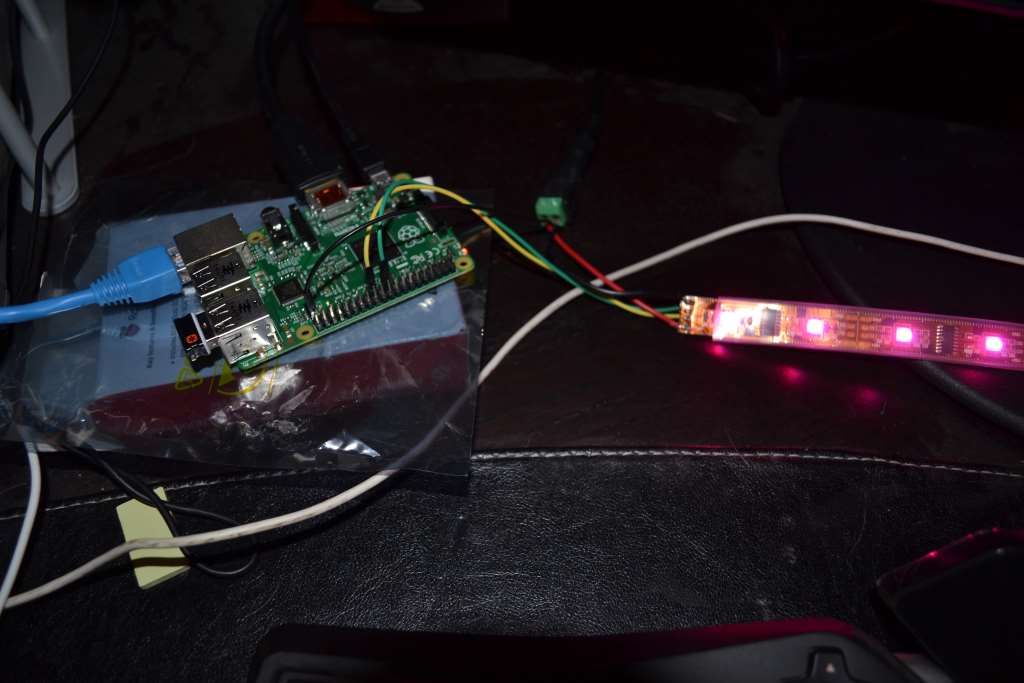 Raspberry Pi2 with LPD8806
A basic XAML GUI with Caliburn.Micro and Autofac.
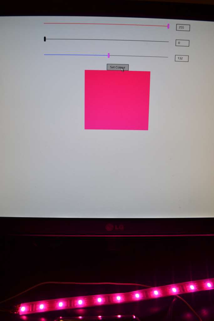 Windows IoT XAML GUI